24th Aug 2026
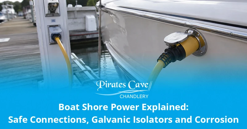
Boat shore power allows a vessel to use marina mains electricity for battery charging and onboard appliances, but it introduces mains-voltage shock, fire and corrosion risks. The installation needs a marine-rated inlet, lead, protective earth, correctly designed circuit protection and regular inspection. A galvanic isolator or isolation transformer may reduce corrosion associated with the shore-earth connection, but neither substitutes for safe wiring or fault protection.
This guide explains what an owner can inspect and understand without presenting mains rewiring as a DIY job. Pirates Cave supplies shore-power equipment, including shore-power cordsets, plugs, sockets and inlets and galvanic isolators.
Never disconnect the protective-earth conductor to reduce anode wear. It is a safety path for fault current. Corrosion concerns must be addressed with a correctly designed electrical and cathodic-protection system, not by defeating shock protection.
Contents
- Key facts at a glance
- What a boat shore-power system contains
- Checks before connecting
- Safe connection and disconnection
- RCDs, RCBOs and circuit breakers
- Choosing and inspecting leads, plugs and inlets
- Why shore power can affect corrosion
- Galvanic vs stray-current corrosion
- Galvanic isolator vs isolation transformer
- Troubleshooting rapid anode wear
- Long-term and winter shore-power use
- Battery charging and load management
- Fault symptoms and immediate actions
- Owner checks vs professional work
- Frequently asked questions
- Technical references
Key facts at a glance
- UK marina shore power is commonly a 230V AC supply and can be lethal.
- Use marine-rated connectors, leads and inlets with the correct voltage, current rating and environmental protection.
- The shore supply, boat inlet, onboard distribution and connected equipment all form part of the safety chain.
- An RCD detects certain leakage-current imbalances; an overcurrent breaker protects against overload and short circuit. They perform different jobs.
- The protective-earth conductor must remain continuous through the intended safety system.
- A damaged, hot, wet, loose or discoloured connector should be isolated and removed from service.
- A galvanic isolator is installed in the protective-earth path and is designed to block small galvanic voltages while passing fault current within its rating.
- An isolation transformer removes direct electrical continuity between shore and vessel systems when correctly installed.
- Neither device cures a DC stray-current fault inside the boat.
- Repeated RCD trips, electric shocks, overheating or very rapid anode loss require competent investigation.
What does a boat shore-power system contain?
| Component | Purpose | Owner-level check |
|---|---|---|
| Marina outlet and protective device | Supplies the allocated berth and provides shore-side protection | Use only the assigned outlet; report damage, water ingress or failed controls to marina staff |
| Shore-power cordset | Carries electricity from pedestal to boat | Inspect full length, plug, connector, locking rings and strain relief |
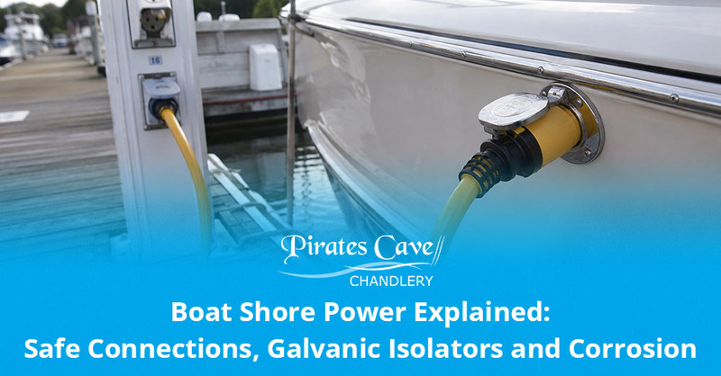
| Boat inlet | Creates the weather-resistant connection to the vessel | Check lid, pins, seal, locking action, heat marks and secure mounting |
| Main double-pole isolation/protection | Allows onboard isolation and protects the incoming circuit | Know its location and labels; test only as the maker instructs |
| RCD or RCBO | Disconnects supply under qualifying leakage conditions | Use the test button at the stated interval; a test button does not replace instrument testing |
| AC distribution panel | Controls and protects individual circuits | Check labels, breaker operation and signs of heat or moisture |
| Protective-earth and bonding arrangement | Provides fault-current path and interacts with corrosion control | Do not modify; investigate loose or corroded connections professionally |
| Galvanic isolator or isolation transformer | Manages the shore-earth galvanic path within its design | Check status indicators and service instructions; installation/testing is specialist work |
| Battery charger and appliances | Use the AC supply | Check current demand, ventilation, cable condition and equipment approval |
Small-craft electrical standards address the design, construction and testing of onboard AC and DC installations. An installation that has grown through years of adapters and owner modifications should be surveyed rather than assumed safe because the appliances appear to work.
Checks before connecting to marina shore power
- Read the marina’s instructions. Connection order, outlet allocation and switching arrangements can vary.
- Confirm compatibility. Match voltage, frequency, current rating, plug type and polarity arrangement to the vessel.
- Inspect the pedestal. Do not use a cracked, loose, submerged, burnt or obviously damaged outlet.
- Inspect the entire cordset. Look for cuts, crushing, taped repairs, flattened sections, corrosion and damaged locking rings.
- Inspect the boat inlet. Pins should be clean, secure and free from heat discolouration.
- Switch off major onboard loads. Avoid connecting while chargers, heaters and other high-demand equipment are already drawing power.
- Keep connectors dry and supported. The lead must not fall into the water, lie in a flooded gutter or create a trip hazard.
- Use only the allocated outlet. Do not daisy-chain boats or split a berth supply with improvised adapters.
Can you use a household extension lead?
A domestic extension is not designed as a substitute for a marine shore-power cordset. Marina connectors need suitable current rating, mechanical strength and environmental protection. Household plugs, reels and couplers exposed to water create serious risk.
Should a cable reel be fully unwound?
Follow the reel or cordset rating. A coiled cable carrying a significant load can retain heat and may have a much lower coiled current rating. Marine cordsets should also be laid so they are protected from vehicles, sharp edges, chafe and immersion.
How should shore power be connected and disconnected?
Always follow the written instructions for the marina, vessel and equipment. A commonly published sequence is to switch the supply and onboard loads off, connect the boat end first and then the shore outlet, before energising the circuit. Disconnection is normally the reverse, beginning by switching off and disconnecting the shore end.
That sequence reduces the chance of carrying a live loose connector along the pontoon, but it must not override site-specific controls. Never force a connector or handle exposed pins while energised.
| Stage | Good practice | Stop immediately if |
|---|---|---|
| Before connection | Loads off; dry hands; correct outlet and lead confirmed | Water, damage, corrosion or incompatible connector is found |
| Boat-end connection | Insert fully and secure the locking system without strain | Pins are loose, connector rocks or locking ring will not engage |
| Shore-end connection | Keep lead supported and follow pedestal switching instructions | Outlet is damaged, wet, unlabelled or not assigned to the berth |
| Energising | Switch on supply, then main protection and loads one at a time | RCD trips, reverse-polarity warning appears, arcing or smell occurs |
| During use | Keep lead visible, dry and cool; manage total load | Plug warms significantly, discolours, crackles or repeatedly trips |
| Disconnecting | Loads off; isolate supply; disconnect shore end as instructed | Connector is hot, seized or wet: isolate and obtain assistance |
What is the difference between an RCD, RCBO and circuit breaker?
| Device | Main function | What it does not guarantee |
|---|---|---|
| Overcurrent circuit breaker | Trips for overload or short-circuit current above its characteristic | It may not trip for a small current leaking through a person or into water |
| RCD | Compares current in live and neutral and trips when the imbalance exceeds its threshold | It does not provide overload protection unless combined with one |
| RCBO | Combines residual-current and overcurrent functions for a circuit | It does not make damaged equipment or poor earthing safe |
| Fuse | Opens when current and time exceed its characteristic | It does not normally provide dedicated residual-current protection |
| Main isolator | Provides a means of switching off the installation | It is not automatically a protective trip device unless designed as one |
An RCD test button confirms part of the mechanism; it does not prove trip time, earth continuity, polarity or every downstream circuit. Periodic instrument testing should be performed by a competent marine electrician.
Repeated trips are a warning, not an inconvenience. Do not keep resetting an RCD or replace a breaker with a larger rating. Isolate loads and have the fault located.
How to choose and inspect shore-power leads, plugs and inlets
Match every component to the installation:
- system voltage and frequency
- maximum supply current, commonly 16A or 32A in UK leisure marinas
- connector pattern and keying
- cable conductor size and overall length
- water and impact resistance
- locking and strain-relief method
- boat inlet material and mounting
- applicable standards and manufacturer approvals
Why long, thin leads overheat
Every conductor has resistance. Excessive length, inadequate conductor area, poor contacts or damaged terminations create voltage drop and heat. The highest temperature often develops at a loose or corroded pin rather than along the visible cable.
When should a cordset be replaced?
Remove it from service when the insulation is cut or crushed, strain relief has failed, pins are pitted or loose, the body is cracked, it has overheated, or an unauthorised repair is present. Replacement connectors must be fitted and tested correctly; wrapping damage in tape is not a marine repair.
Browse complete shore-power cordsets, individual shore-power plugs and shore-power sockets and inlets.
Why can shore power increase galvanic corrosion?
When a boat is connected to shore power, its protective-earth conductor may create an electrical connection to marina infrastructure and other connected vessels. Submerged dissimilar metals can then form a wider galvanic circuit through conductive water and the earth network.
The small voltage involved can drive current that consumes sacrificial anodes or attacks vulnerable underwater metal. The protective earth is nevertheless essential for electrical safety and must remain in the intended circuit.
Read The Ultimate Boat Anode Guide for a fuller explanation of galvanic corrosion, bonding and abnormal anode wear.
Why neighbouring boats behave differently
Two boats on the same pontoon can have different immersed metals, anode alloys, coatings, bonding systems, wiring faults and shore-power protection. One may remain connected continuously while another connects for a few hours. Their anode lives will not necessarily match.
Galvanic corrosion vs stray-current corrosion
| Feature | Galvanic corrosion | Stray-current corrosion |
|---|---|---|
| Driving source | Natural voltage between dissimilar metals | Unintended current from an electrical source |
| Typical voltage/current | Relatively small galvanic potential | Can be much larger and more destructive |
| Path | Metals, water and electrical connection | Faulty DC/AC circuit, water and unintended return path |
| Anode effect | Normal or accelerated sacrificial consumption | Anodes may disappear rapidly but cannot repair the fault |
| Correct response | Verify anode system, bonding and shore-earth isolation strategy | Locate and repair the electrical leakage immediately |
| Galvanic isolator | Can address low-voltage galvanic current through shore earth when correctly specified | Does not cure general DC leakage from onboard wiring |
Rapid pitting concentrated around one fitting, major change after electrical work, shocks, tingling or anodes disappearing within weeks can indicate more than ordinary galvanic action.
Galvanic isolator vs isolation transformer
| Feature | Galvanic isolator | Isolation transformer |
|---|---|---|
| Basic principle | Semiconductor device in the shore protective-earth path blocks small galvanic voltages within its design | Transfers AC energy magnetically and removes direct electrical continuity between shore and vessel systems |
| Protective earth | Remains a fault-current path through the device | Shore earth and vessel-side earthing are arranged through the transformer design |
| Size and cost | Generally smaller and less expensive | Larger, heavier and usually more expensive |
| Voltage conversion | No | Some models can provide voltage conversion or compensation |
| Installation | Must be correctly rated, located and tested so it cannot be bypassed | Requires designed AC installation, ventilation, protection and earthing |
| Stray-current fault | Does not repair it | Does not repair an onboard DC leakage fault |
| Failure monitoring | Fail-safe standards/status monitoring may apply by product | Thermal, overload and installation protections are product-specific |
| Best selection basis | Vessel standard, shore current, corrosion survey and installer recommendation | System design, power demand, space, weight and professional specification |
What does a galvanic isolator do?
A correctly specified galvanic isolator blocks low-level galvanic voltage on the shore-earth connection while allowing higher fault current to pass so protective devices can operate. It must be installed before paths that could bypass it and should be tested according to its design and applicable standard.
What does an isolation transformer do?
An isolation transformer supplies the boat through a magnetically coupled secondary winding, so there is no direct conductive connection between shore and vessel systems in the designed afloat configuration. Vessel-side neutral and earth arrangements, RCDs and out-of-water configurations are technical matters for the manufacturer and installer.
Installation warning: fitting a galvanic isolator or isolation transformer changes a safety-critical protective system. It is not an owner-level two-wire accessory job. Use a competent marine electrician and obtain the required testing documentation.
Why are the boat’s anodes disappearing quickly on shore power?
Possible causes include:
- normal increased galvanic coupling through the marina earth
- missing, failed, underspecified or bypassed galvanic isolator
- incorrect anode alloy or insufficient protection for the equipment
- loose bonding conductors or poor anode contact
- DC leakage from the boat or a neighbouring source
- new stainless-steel, bronze or aluminium equipment changing the galvanic balance
- damaged underwater coating increasing exposed metal area
- a berth with different salinity, temperature or electrical environment
A sensible investigation sequence
- Record anode alloy, installation date and photographic condition.
- Confirm the anodes are the specified parts and make clean electrical contact.
- Compare wear while connected and disconnected only as part of a planned professional test, not by removing safety earth.
- Have shore lead, polarity, RCD operation, earth continuity and onboard leakage tested.
- Test the galvanic isolator or transformer to its manufacturer procedure.
- Inspect bonding, underwater fittings and recent electrical modifications.
- Use a corrosion-potential survey when the cause remains unclear.
Leaving a boat connected to shore power over winter
Continuous connection increases exposure time to electrical faults, connector heating and galvanic paths. It may be necessary for battery charging, heaters, dehumidification, alarms or pumps, but the arrangement should be designed for unattended use.
Before leaving the boat:
- confirm the marina permits unattended connection
- inspect the lead and ensure it cannot enter the water
- reduce loads to those genuinely required
- use equipment approved for continuous marine operation
- confirm ventilation around chargers and transformers
- test alarms and monitoring
- schedule physical inspections after storms and high water
- monitor battery temperature and charging behaviour
- record anode condition more frequently
Are portable fan heaters safe unattended?
Portable heaters can tip, overheat, draw high current and ignite nearby material. Follow marina and insurer rules and do not leave an appliance unattended unless it is expressly designed and installed for that service.
Battery charging and shore-power load management
Total AC load must stay below the lowest relevant limit: marina outlet, shore lead, inlet, main breaker and onboard distribution. A 16A supply does not mean every appliance can run together.
Approximate single-phase power
Power (W) = Voltage (V) × Current (A)
At a nominal 230V, 16A corresponds to about 3,680W in ideal arithmetic. Allow for actual voltage, equipment characteristics and the installation rating; do not operate continuously at an assumed theoretical maximum.
Battery chargers can draw heavily when batteries are low, while kettles, water heaters and fan heaters add large simultaneous loads. Browse marine battery chargers only after matching battery chemistry, bank voltage, capacity and shore supply.
Shore-power warning signs and immediate actions
| Warning sign | Immediate action | Likely investigation |
|---|---|---|
| Plug, lead or inlet feels hot | Switch off and disconnect safely; do not continue using it | Loose/corroded contact, overload, damaged cable or inadequate rating |
| Burning smell, smoke or crackling | Isolate supply, raise alarm and follow fire procedure | Arcing, overheating or equipment failure |
| RCD trips repeatedly | Leave circuit isolated; disconnect loads only when safe | Leakage, wet connector, failed appliance or wiring fault |
| Reverse-polarity warning | Do not use supply | Pedestal, adapter or onboard wiring error |
| Shock or tingling from metalwork/water | Do not touch or enter water; isolate and alert marina/emergency services | Dangerous earth/leakage fault requiring urgent specialist response |
| Rapid anode loss | Increase inspection; arrange corrosion/electrical survey | Galvanic path, isolator fault, bonding issue or stray current |
| Green corrosion or water in connector | Remove from service and replace/repair professionally | Seal failure and conductive contamination |
| Charger unusually hot or batteries gassing | Isolate charger if safe and ventilate; keep sparks away | Wrong charge profile, battery fault or inadequate ventilation |
What can an owner check, and what needs a marine electrician?
| Suitable owner inspection | Professional electrical work |
|---|---|
| Visual inspection of lead, plugs, inlet and labels | Opening, modifying or replacing the AC distribution system |
| Operating user test buttons as instructed | Instrument tests of RCD trip time, polarity and earth continuity |
| Keeping connectors dry, supported and clean externally | Fitting or testing a galvanic isolator or isolation transformer |
| Recording trips, heat, corrosion and anode wear | Tracing leakage current and bonding faults |
| Managing appliance load within known ratings | Changing breaker, cable or inlet ratings |
| Following approved connection procedure | Designing inverter/charger changeover and generator integration |
Qualified work should be documented with test results and an updated circuit diagram. Tell the electrician about inverters, generators, solar, battery chargers and any automatic changeover system; these sources can remain live even when the shore lead is unplugged.
Choose shore-power components as a complete safety system
Browse shore-power equipment, including cordsets, plugs, sockets and galvanic isolators.
Before ordering, identify the shore voltage/current, existing inlet and connector, cable length, onboard protection, continuous loads and corrosion symptoms. Contact Pirates Cave for product help, and use a competent marine electrician for installation and testing.
Frequently asked questions about boat shore power
What is shore power on a boat?
It is an external AC electricity supply connected from a marina outlet to the vessel. It commonly powers a battery charger and onboard mains circuits while the boat is berthed.
Can I leave my boat connected to shore power all the time?
Only when the marina permits it and the installation, cordset, charger and connected equipment are designed for unattended continuous operation. Inspect regularly and manage galvanic-corrosion exposure.
What size shore-power lead do I need?
Match voltage, current rating, connector type, conductor size and length to the berth and boat installation. The lead must not have a lower rating than the protective arrangement it serves.
Can I plug a 16A boat into a 32A marina outlet?
Only through an approved arrangement that provides correct connector adaptation and overcurrent protection for the lower-rated boat circuit. A simple physical adapter may leave the smaller lead inadequately protected.
Why does my shore-power plug get hot?
Common causes include loose, corroded or worn contacts, overload, inadequate cable size and poor termination. Switch off and remove it from service; heating can lead to fire.
What does an RCD do on a boat?
It compares current flowing in live and neutral and disconnects when an imbalance exceeds its threshold. It reduces risk from certain earth-leakage faults but does not replace correct earthing or overcurrent protection.
Why does the RCD trip when I connect shore power?
Possible causes include a wet lead or inlet, faulty appliance, neutral-earth issue, wiring leakage or incompatible source/changeover arrangement. Leave it isolated and have the fault tested.
Do I need a galvanic isolator?
It may be appropriate when a boat connects its protective earth directly to marina shore power, but selection depends on installation standard, current rating and corrosion design. Obtain professional advice.
Does a galvanic isolator stop electrolysis?
It is designed to block low-voltage galvanic current in the shore-earth path. It does not stop every form of corrosion and cannot repair a DC stray-current fault.
Is an isolation transformer better than a galvanic isolator?
An isolation transformer provides fuller electrical separation from shore but is larger, heavier and more expensive. The best solution depends on vessel design, power demand, space and professional specification.
Can I disconnect the earth wire to save my anodes?
No. Removing protective earth can leave metalwork live without causing the intended protective device to operate. Use a correctly designed isolator or transformer system instead.
Can shore power make anodes wear faster?
Yes. The earth connection can join the boat into a wider galvanic circuit. Rapid wear can also indicate an isolator, bonding or stray-current fault and should be investigated.
Should the shore lead be disconnected before working on batteries?
Isolate all energy sources according to the vessel procedure. Chargers, inverters, solar and generators can energise circuits independently, so unplugging the shore lead alone may not make the system safe.
Can a boat use shore power while out of the water?
Only with the yard’s approval and the transformer/earthing arrangement configured exactly as specified for ashore use. Some systems require a different earth link when hauled out. This is professional work.
How often should shore-power equipment be tested?
Visually inspect before each connection, use user test buttons at the manufacturer’s interval and arrange periodic instrument testing based on standards, insurer, coding and vessel use. Harsh conditions may require shorter intervals.
Technical references
- ISO 13297:2020: Small craft electrical systems
- Institution of Engineering and Technology: Boat wiring and marine standards
- Victron Energy: Isolation transformer manual and earthing principles
- Victron Energy: Galvanic isolator installation manual
- Royal Yachting Association: Electrical-systems maintenance
Important: Mains electricity aboard is safety-critical. This guide supports inspection and purchasing decisions, not installation. Standards and equipment instructions can change, and the correct design depends on the complete vessel system. Use a competent marine electrician for alterations, fault-finding and formal testing.